Scratch Testing of Thermal Spray Coatings Introduction
Thermal spraying is a coating technique in which melted material is projected onto a surface to coat it. Compared to other deposition techniques, the thermal sprays offer the ability to cover large area at high deposition rates and provide thicker coatings. Thermal sprays are used in various industries such as aerospace, automobile, marine and heavy machinery. The applications for those coatings cover wear and abrasion resistance, low friction, corrosion protection, altering thermal and electrical conductivity and many others.
Need help or have a question?
Scratch Test Problematic
The projection of melted material onto the substrate surface forms a highly inhomogeneous coating. This consisting of a multitude of “pancake-like” splats called lamellae formed by the flattening of the material droplet. The size of those lamellae along with the varying degrees of porosity are typically used to characterize the thermal spray coatings. But this deposition technique results in a unique microstructure that presents properties significantly different than bulk materials. The different types of thermal spraying processes (flame, arc, plasma, high velocity oxy fuel and detonation gun spraying ) also increase the complexity of the material problematic by yielding different structures. The durability and functionality of these coatings is highly dependent on the cohesion strength of the resulting coating but also on its adhesion to the substrate. It is therefore necessary to test those coating in their “as deposited” state to investigate the effects of deposition techniques, spraying parameters such as velocities, and substrate surface preparation.
Scratch Test Methodology
The substrate / thermal spray system is mounted as a cross section in a metallographic mount and polished to expose the interface between the substrate and coating. A constant load scratch is generated by dragging a spheroconical diamond tip perpendicular to the interface and moving from the substrate towards the coating (Figure 1). The scratch is set up to finish in the mounting material.
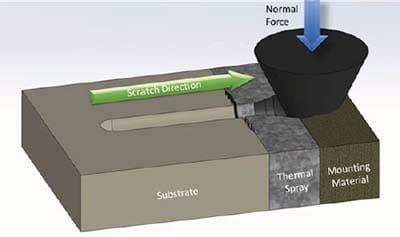
Figure 1: Cross sectional Scratch Testing principle
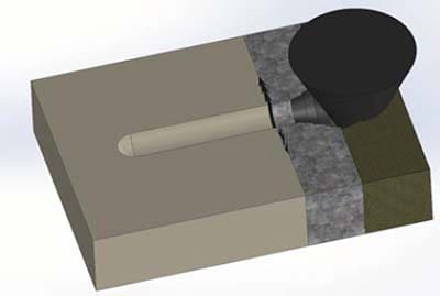
Figure 2: Cross sectional Scratch Testing failures
Two main types of failures can be created as shown in Figure 2 :
- Cohesive failure as exhibited by cracks inside the thermal spray coating and conical fracture of the coating at the free surface
- Adhesive failure if some cracks develop at the interface between the substrate and the thermal spray coating.
Scratch Test Conditions
| Load Application Profile | Constant Load |
| Scratch Length | 2 mm |
| Constant Load | 20 & 30 N |
| Scratch Speed | 4 mm/min |
| Stylus | Rockwell with 200 µm radius |
Three scratches per load (Figure 3) are performed on each sample for a total of 6 scratches per sample. The constant loads were chosen to create enough damage and the possibility to test adhesion failure.

Figure 3: Cross Section Testing on the SMT-5000
Thermal Spray Coating Adhesion Test Results
Four different thermal sprays cross sections mounted in metallographic mounts were tested to investigate properties of coatings – cohesion and adhesion.
Different types of failures can be observed in the coatings:
Adhesive Failure
In this case, the cracks developed at the interface between the thermal spray and the substrate. This failure is directly related to the strength of adhesion that exists between the thermal spray coating and the substrate. The cracks always originate from the interface and can either propagate along the interface or inside the coating.
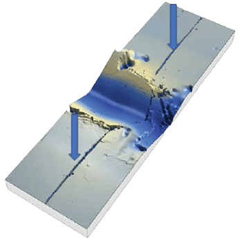
Figure 4: Adhesion Failure at the interface
The lengths of the cracks on either side of the scratch groove can be used to quantify the severity of the adhesion failure. When this failure is observed, no other conclusion can be made as most of the energy of the test goes into failing the coating / substrate interface.
Cohesive Failure in Coating
This type of failure is characterized by some cracks propagating from the side of the scratch groove into the coating itself. Both the origin and end of the cracks are located into the thermal spray coating.
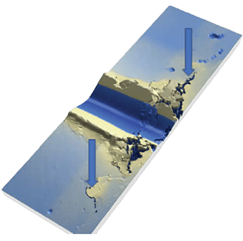
Figure 5: Cohesion failure in the coating
This failure relates directly to the strength of the coating itself as it is contained in its domain.
Cohesive Failure at the Free Surface
The final type of failure is seen at the free surface of the thermal spray coating and is typically in the shape of a cone. This failure relates also to the cohesion of the thermal spray coating but demonstrate a higher cohesion than cracks happening inside the coating. This failure is the result of the thermal spray failing towards its free surface.
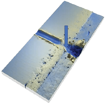
Figure 6: Cohesive failure at the free surface of coating
Granted that no other failure is observed prior to the free surface, the samples exhibiting this failure can be ranked by measuring the angle of the conical failure.
A lower angle will correspond to a higher cohesion of the thermal spray.
Comparison of Thermal Spray Samples
1. Can adhesion failure be seen at the interface? If adhesion failure is seen, no other comparison can be made, and these coatings will be the lowest ranking. If the coating cannot adhere to the substrate, the cohesion of such coating does not matter as it will fail at the interface prior to failing cohesively. If several samples exhibit adhesion failures, the length of the cracks at the interface is used to differentiate them.
2. If no adhesion failure is seen, can cohesive failure be seen inside the coating? Cohesive failure inside the coating will be the next level of ranking as the interface is strong and the coating is now failing internally. If multiple samples exhibit cohesive failure inside the coating, the length of the cracks inside the coating is used to rank them from small crack to longer crack.
3. If no adhesion failure at the interface and no cohesive failure in the coating are seen, the cohesive failure at the free surface becomes the focus. The last point of failure is situated at the free surface of the coating, as the scratch is moving into the mounting material which is often much softer than the coating. In this case the samples are ranked with the measurement of the angle of the fracture at the free surface as shown in Figure 4.
For the comparison of these two thermal sprays, the “exit” cone angle is measured as the tip scratches from the thermal spray to the mounting material. This angle is representative of the strength of the coating where a stronger coating will exhibit a smaller fractured angle as it is the case for TS 3.


Figure 7: TS 1 & TS 3 angle measurements
Scratch Testing of Thermal Spray Coatings Results Summary
In this study, the four thermal spray samples
exhibited different failures from adhesion to cohesion. The results of all samples are summarized in Table 2.
| Sample | Y/N | Total crack length (µm) |
|---|---|---|
| TS 1 | N | |
| TS 2 | N | |
| TS 3 | N | |
| TS 4 | Y | 357 |
| Sample | Y/N | Total crack length (µm) |
|---|---|---|
| TS 1 | N | |
| TS 2 | Y | 124 |
| TS 3 | N | |
| TS 4 |
| Sample | Y/N | Angle of fracture con (deg) |
|---|---|---|
| TS 1 | Y | 71.54 |
| TS 2 | ||
| TS 3 | Y | 58.24 |
| TS 4 |
The adhesion failure of TS 4 brings it to the bottom of the ranking for those samples. TS 2 exhibits good adhesion but cohesion failure in the coating whereas TS 1 and TS 3 are at the top of this samples ranking. As explained above the differentiation between those two is done using the angle of the fractured cone. This measure yields TS 3 as the best coating of this group with a smaller angle.
Conclusions
The scratch testing technique is used here to characterize both adhesion and cohesion of thermal sprays as sprayed on their respective substrates. A single test can yield a deeper understanding of the strength of the thermal spray coatings. In turn, the observation and quantification of failures helped our customer adjust the substrate surface preparation for TS 4 and the spraying parameters for TS 1 to 3 in order to increase the adhesion and cohesion of their coatings. Not described in this study, the same coatings were also tested for wear and coefficient of friction using Rtec Instruments MFT 5000. The combination of scratch testing and tribology testing (wear/COF) gives a more complete understanding of those coating and their resistance to mechanical forces. Rtec Instruments is uniquely qualified and positioned for the characterization of such coating.
References
1 By Matthias Zepper – Selbst aufgenommen bei Vorführung der Anlage im Institut für Technische Thermodynamik (Pfaffenwaldring 38-40 in D-70569 Stuttgart) des Deutschen Zentrums für Luft und Raumfahrt (DLR)., CC BY-SA 2.5
2 ISO 27307 – 2015 Thermal spraying — Evaluation of adhesion/cohesion of thermal sprayed ceramic coatings by transverse scratch testing
3 Lopez, Zambelli, Cohesion measurement of plasma sprayed ceramic coatings, Surface Modification Technologies (815-821), 1990

The Scratch and Indentation Tester Has More To Offer
Learn more about our Indentation and Scratch Tester, the SMT-5000.

Need Versatile Scratch and Indentation Testing?
Take a look at the Multi Function Tribometer, the MFT-5000.
Want to learn more?
Get in touch, and request a demo.
Leading innovation in surface and materials testing instrumentation.
recommended
Information
© Copyright 2021 Rtec-Instruments - All Rights Reserved