Scratch Testing of Thermal Spray Coatings Introduction
Brauchen Sie Hilfe oder haben Sie eine Frage?
Scratch Test Problematic
Scratch Test Methodology
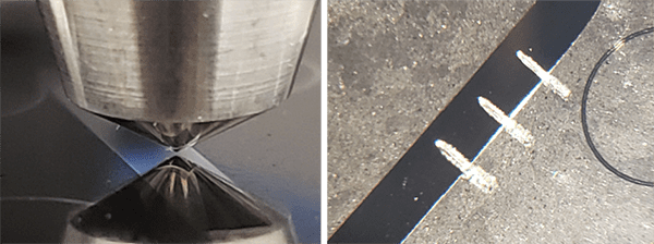
The substrate / thermal spray system is mounted as a cross section in a metallographic mount and polished to expose the interface between the substrate and coating. A constant load scratch is generated by dragging a spheroconical diamond tip perpendicular to the interface and moving from the substrate towards the coating (Figure 1). The scratch is set up to finish in the mounting material.
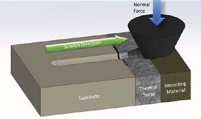
Figure 1: Cross sectional Scratch Testing principle
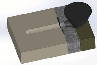
Figure 2: Cross sectional Scratch Testing failures
- Cohesive failure as exhibited by cracks inside the thermal spray coating and conical fracture of the coating at the free surface
- Adhesive failure if some cracks develop at the interface between the substrate and the thermal spray coating.
Scratch Test Conditions
| Load Application Profile | Constant Load |
| Scratch Length | 2 mm |
| Constant Load | 20 & 30 N |
| Scratch Speed | 4 mm/min |
| Stylus | Rockwell with 200 µm radius |
Three scratches per load (Figure 3) are performed on each sample for a total of 6 scratches per sample. The constant loads were chosen to create enough damage and the possibility to test adhesion failure.
Thermal Spray Coating Adhesion Test Results
Four different thermal sprays cross sections mounted in metallographic mounts were tested to investigate properties of coatings – cohesion and adhesion.
Different types of failures can be observed in the coatings:
Adhesive Failure
In this case, the cracks developed at the interface between the thermal spray and the substrate. This failure is directly related to the strength of adhesion that exists between the thermal spray coating and the substrate. The cracks always originate from the interface and can either propagate along the interface or inside the coating.
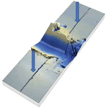
Figure 4: Adhesion Failure at the interface
The lengths of the cracks on either side of the scratch groove can be used to quantify the severity of the adhesion failure. When this failure is observed, no other conclusion can be made as most of the energy of the test goes into failing the coating / substrate interface.
Cohesive Failure in Coating
This type of failure is characterized by some cracks propagating from the side of the scratch groove into the coating itself. Both the origin and end of the cracks are located into the thermal spray coating.
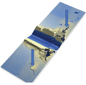
Figure 5: Cohesion failure in the coating
This failure relates directly to the strength of the coating itself as it is contained in its domain.
Cohesive Failure at the Free Surface
The final type of failure is seen at the free surface of the thermal spray coating and is typically in the shape of a cone. This failure relates also to the cohesion of the thermal spray coating but demonstrate a higher cohesion than cracks happening inside the coating. This failure is the result of the thermal spray failing towards its free surface.
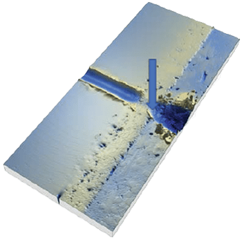
Figure 6: Cohesive failure at the free surface of coating
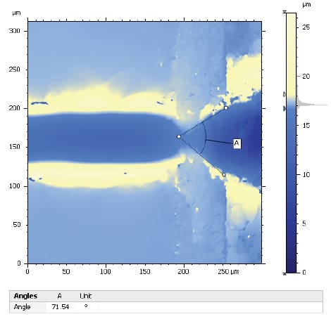
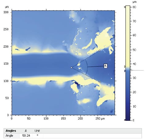
Granted that no other failure is observed prior to the free surface, the samples exhibiting this failure can be ranked by measuring the angle of the conical failure.
A lower angle will correspond to a higher cohesion of the thermal spray.
Comparison of Thermal Spray Samples
Figure 7: TS 1 & TS 3 angle measurements
Scratch Testing of Thermal Spray Coatings Results Summary
In this study, the four thermal spray samples
exhibited different failures from adhesion to cohesion. The results of all samples are summarized in Table 2.
| Sample | Y/N | Total crack length (µm) |
|---|---|---|
| TS 1 | N | |
| TS 2 | N | |
| TS 3 | N | |
| TS 4 | Y | 357 |
| Sample | Y/N | Total crack length (µm) |
|---|---|---|
| TS 1 | N | |
| TS 2 | Y | 124 |
| TS 3 | N | |
| TS 4 |
| Sample | Y/N | Angle of fracture con (deg) |
|---|---|---|
| TS 1 | Y | 71.54 |
| TS 2 | ||
| TS 3 | Y | 58.24 |
| TS 4 |
Conclusions
References
2 ISO 27307 – 2015 Thermal spraying — Evaluation of adhesion/cohesion of thermal sprayed ceramic coatings by transverse scratch testing
3 Lopez, Zambelli, Cohesion measurement of plasma sprayed ceramic coatings, Surface Modification Technologies (815-821), 1990
The Scratch and Indentation Tester Has More To Offer
Need Versatile Scratch and Indentation Testing?
Möchten Sie mehr erfahren?
Kontaktieren Sie uns und fordern Sie eine Demonstration an.
recommended
Information
© Copyright 2021 Rtec-Instruments - All Rights Reserved

