Quality Control of Hard Coatings Introduction

Figure 1: Typical applications of PVD coatings: inserts and cutting tools
Brauchen Sie Hilfe oder haben Sie eine Frage?
Principles of Testing
“The scratch test is designed for the assessment of the mechanical integrity of coated surfaces. The test method consists of generating scratches with a stylus of defined shape (usually a diamond with a Rockwell C geometry) by drawing it across the surface of the coating-substrate system to be tested, either under a constant or progressive normal force (Fig.2). Failure events are detected by direct microscopic observation of the scratch and sometimes by using acoustic emission and/or friction force measurement.”


A test with constant or increasing forces can be considered. The interest of the increasing force is to determine in a single test the critical loads, and therefore the critical stresses, at which the cohesive and/or adhesive failures are observed. By a relatively quick test, the critical load for which the coating adhesion is failing can be measured, as shown on Fig. 3.
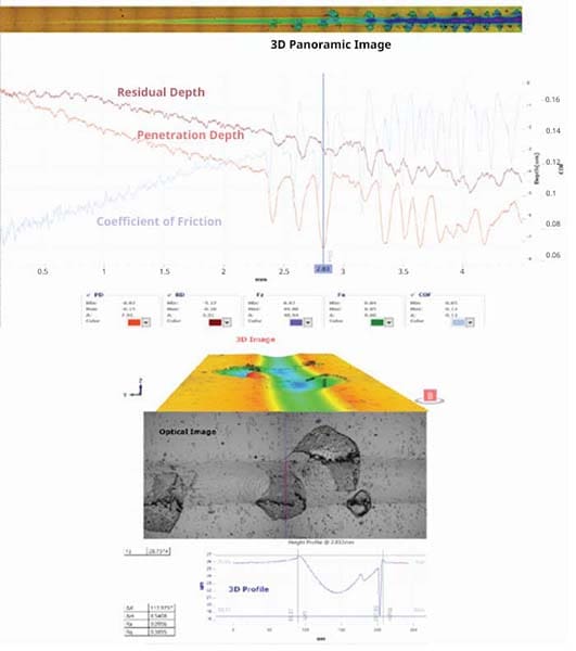
Figure 3. Principles of the data analysis of the scratch results with in-line 3D imaging on a TiN coating
Characterization Method
Differences between failure modes are interesting to observe: adhesive failure (delamination at the interface coating-substrate, typically observed on DLC coatings) or cohesive failure (spallation inside the coating, typically observed on TiN coatings) provide an interesting view on the mechanical strength of the sample (see Fig. 4).
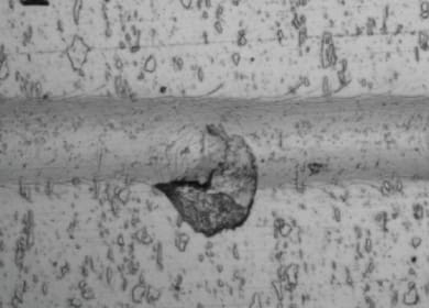
Figure 4a: Cohesive Spallation
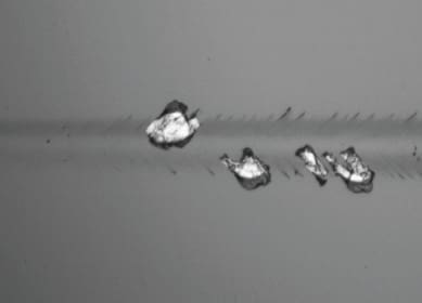
Figure 6c Lc3: Full Delamination
The critical normal force, Lc, is linked therefore to the mechanical integrity of a coating-substrate system (or multilayer coating-substrate). The mechanical stresses in the system can be schematically represented as on Fig. 5.


The Lc1 is generally considered as the appearance of the first cracks, the Lc2 as the first delamination or spallation, and the Lc3 as the full delamination. Examples of Lc1, Lc2 and Lc3 are illustrated on Figure 6a-c.
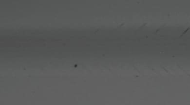
Figure 6a Lc1: First Cracks
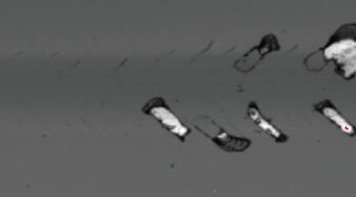
Figure 6b Lc2: First Delamination
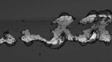
Figure 6c Lc3: Full Delamination
The determination of the critical normal force, Lc(n), also commonly accepted name of critical loads, Lc(n), could represent the aspect of testing which is the most subject to interpretation. The challenge may lie on two aspects:
- Difficulty of detection: typical cracks in hard coatings can be detected with the Acoustic Emission (AE) sensor but can be difficult to observe optically. It is therefore worthwhile to investigate which detection method (microscopy,
penetration depth, AE or friction) is the more valuable for this detection; - Misinterpretation: some failure modes can be interpreted differently by various users.
But in Quality Control, these errors can be easily eliminated from the beginning on the first study. The modes of failures on a specified coating-substrate system are highly reproducible (i.e TiN coatings show typical cohesive failures while DLC coatings tend to display adhesive failures). It is also easier to decide which Lc(n) are the most meaningful without possible misinterpretation.
Specific Aspects for Scratch Testing in Quality Control
Indenter Tip Characterization
One of the essential experimental parameter of influence of the scratch testing method, which can be overlooked, is the exact geometry of the spherical indenter tip and its regular control.
The test by itself corresponds to a strong mechanical interaction between a sphero-conical indenter and a coating surface, for which the results is highly dependent on small variations of the local contact area. Therefore, it is extremely important to regularly check the quality of the tip.
Rtec-Instruments is proposing an integrated confocal microscope to the scratch tester, which allows a fast indenter tip control with a high resolution 3D image. Tip damages or contaminations can be observed easily. A regular cleaning of the tip by ultrasonic bath and/or mechanical polishing is helping to ensure an effective consistent contact area for scratch tests. This process
can be implemented in the control procedure of the scratch testing method.
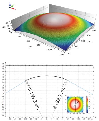
Figure 7: Determination of tip radius with integrated confocal microscope for 3D imaging
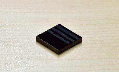
Figure 8. DLC coating used as a certified reference sample
Instrument Verification and Recalibration
The certified reference sample has the significant advantage to provide both at the same time a verification of the instrument and of the scratch indenter tip, the indenter tip being one of the other important parameters to be verified as well.
Geometry and Surface Roughness
Thanks to the advanced force feedback loop control of the measuring heads, the force applied is continuously monitored and the position of the head adapted to the sample geometry. Testing on cylinders and spheres can be performed, the main physical limits being the indenter tip size and geometry in contact with the sample surface. Adaptation of tips can be designed easily for special geometries.
It is recommended to have a uniform statistical roughness, and in the best conditions, the surface roughness Ra, would not exceed 0.5 μm. In real manufactured parts, this ideal value may not be reached but it does not impede to perform scratch tests on very rough surfaces and conduct analysis of results. The only drawback is the higher dispersion of data to be considered. Rtec-Instruments is offering an integrated dual white light interferometer (WLI) and confocal microscope for a full view of mechanical and surface characteristics of hard coatings.
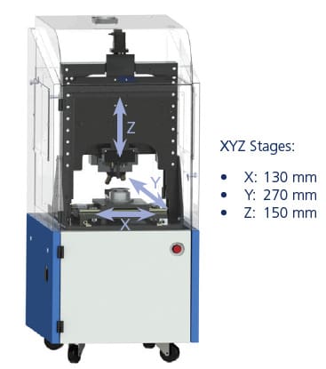
Figure 9. Large automated and motorized platform for programmable scratch tests and 3D images (WLI and confocal)
Automation for Quality Control and Multiple Sample Programming
Modes of Scratch Testing
Progressive-Force Scratch Test
The normal force applied by the indenter increases linearly as the indenter moves across the test surface at constant speed. As the force increases, the indenter gradually penetrates into the layers. As the penetration depth increases, the stresses induced by the diamond increases as well. For hard coatings (2 – 6 mm), with a Rockwell 200 mm radius and following the international standards, we suggest parameter values of 100 N/min and 10 mm/min. If the critical load used for failure is lower than 10 N, a lower loading rate is recommended. During the Scratch, at certain force– the critical loads (Lc) like cracking, spallation, full delamination… are reached, this is the force value (pressure) that causes material the failure.
Constant-Force Scratch Test
The normal force is increased step by step between successive scratches carried out under constant normal force, at different locations on the specimen surface until failure occurs. Using one-fifth of the critical normal force determined by the progressive-force scratch test, a series of scratches are produced at increasing normal force using an indenter traverse speed of 10 mm/min. A new series of scratches using lower normal-force increments can be used to investigate any regions of interest more closely.
The interest of the constant force is to determine either the critical loads of failures with the utmost precision or the uniformity of the sample by scanning large areas of the surface. The constant force can be run in automated multiple tests (with a constant force increased at each test series) in order to obtain statistically and with the highest precision the critical loads of first cracks, first delamination and full delamination.
It happens that for the practical reason of time limitation, the constant-force scratch test has been less used in industrial applications than the progressive-force scratch, because the latter one is much faster while providing reliable enough data.
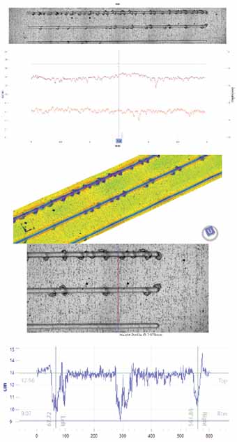
Figure 10. Constant force measurement with integrated 3D imaging
Multi-Pass Scratch Test or Tribological Test
The specimen is subjected to repeated scratching, within the same scratch track, under a constant subcritical normal force. Using a normal force of 50 % of that determined under the progressive-force scratch mode, an indenter traverse speed of 10 mm/min and a scratch length of at least 3 mm, the sample is tested until failure occurs. This mode represents a low-cycle fatigue-type contact, which is closer to the real working conditions, but also more equivalent to a tribological test. The scratch tester can then be used like a tribometer in a linear reciprocating oscillating mode.
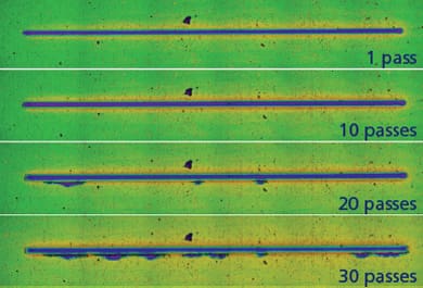
Figure 11a. Evolution of a mutlipass constant scratch at 15 N on TiN
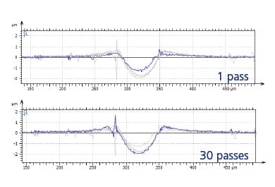
Figure 11b. Superposition of the profile during multipass constant scratch test at 15 N on TiN coating
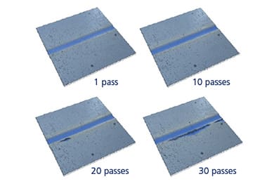
Figure 11c. 3D image of the multiscan at 15 N
Interest of Quality Control with the Scratch Test Method and Conclusions
References
ISO 20502 (2005-reviewed and confirmed in 2019) Fine ceramics (advanced ceramics, advanced technical ceramics) – Determination of adhesion of ceramic coatings by scratch testing.

The Scratch and Indentation Tester Has More To Offer

Need Versatile Scratch and Indentation Testing?
Möchten Sie mehr erfahren?
Kontaktieren Sie uns und fordern Sie eine Demonstration an.
Leading innovation in surface and materials testing instrumentation.
recommended
Information
© Copyright 2021 Rtec-Instruments - All Rights Reserved