Scratch Adhesion and Cohesion of Hard Coatings Introduction
Varying in their composition, hard coatings are typically used to harden the surface of a product. They can be nitrides (Titanium nitride, TiN), carbides (Tungsten carbide, WC) or other types (Diamond like carbon, DLC). Their functionality goes beyond the simple hardening, some are used to protect against corrosion, reduce the wear of a part or avoid the formation of blood clot on materials in contact with blood. They are applied to many different substrates with many different techniques.
This note studies scratch adhesion and cohesion of hard testing using Rtec Indentation and Scratch Tester SMT-5000.
Brauchen Sie Hilfe oder haben Sie eine Frage?
Scratch Test of Hard Coatings Problematic
Given their functionalities, hard coatings need to be characterized both for their inherent strength and for their adhesion to the substrate on which they are deposited. For example, the corrosion resistance of a coating will decrease as soon as the cohesion of the coating is challenged by cracks at the surface. In the case of medical devices, the adhesion of wear-resistant coatings to implants need to guaranty that no coating “chip” can enter the bloodstream, threatening the health of the patient.
But adhesion is a difficult property to quantify as it is not a material property but the response of a coating / substrate system to an applied stress field. The scratch test is often used to induce stresses capable of fracturing the coating and delaminating it from its substrate hence yielding a better understanding of the coating adhesion. The ability to study both cohesion and adhesive failures with one test presents some advantages for both the researchers and the industrial engineers trying to improve their coating products.
Scratch Testing Of Hard Coatings Methodology
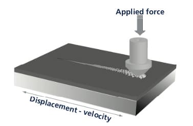
Figure 1: Scratch Testing principle
A scratch is created by dragging a diamond tip of known geometry a top the surface of the sample of interest as shown in Figure 1. As the tip is moved along the surface, the normal load applied to the tip is in- creased linearly, creating an increase in the severity of the contact. Following the scratch, images are taken of the entire scratch to analyze the different deformation and failures.
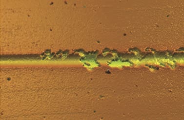
Figure 2: Confocal image of Scratch Failures
The normal loads at which failures happen are called critical loads, LC .
Critical loads are found using either imaging or a combination of imaging and signals (Acoustic emission for example).
Critical loads are found using either imaging or a combination of imaging and signals (Acoustic emission for example).
The critical load representing the failure by removal of the coating is a quantitative proxy for adhesion strength. Multiple signals can be recorded during the scratch test, allowing the user to correlate behaviors and specific measures.
Scratch Adhesion and Cohesion Testing Conditions
The Indentation and Scratch Tester (SMT-5000) was used to create scratches on three hard coatings: TiN and two DLC. The test parameters are summarized in Table 1.
| Load application profile | linear increasing |
| Scratch length | 2 mm |
| Initial load | 0.1 N |
| Final load | 15 N |
| Scratch speed | 4 mm/min |
| Stylus | Rockwell 100mm radius |

Figure 3: Sample in the instrument
Scratch Testing of Hard Coatings Results
In all cases, as the normal force increases, the coatings fail first cohesively and then adhesively figure 4 shows the resulting penetration depth and coefficient of friction for 2 samples as the normal scratch load is increased up to 15N.
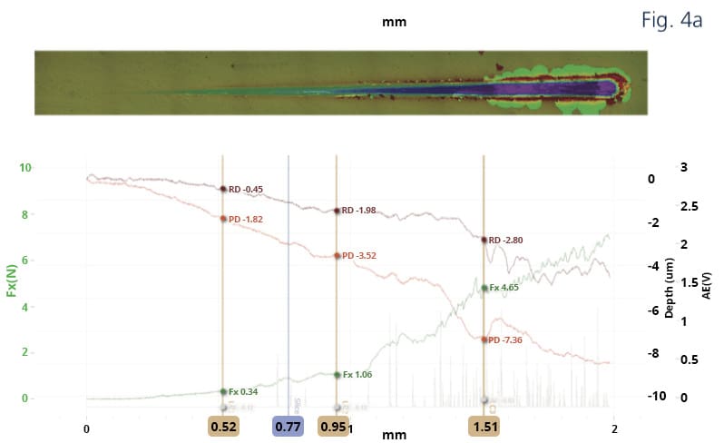
Figure 4: Plots of Penetration depth, Scratch load, coefficient of friction, Acoustic emission along with Critical loads (vertical lines) for DLC 2 (left) and TiN (right) samples.
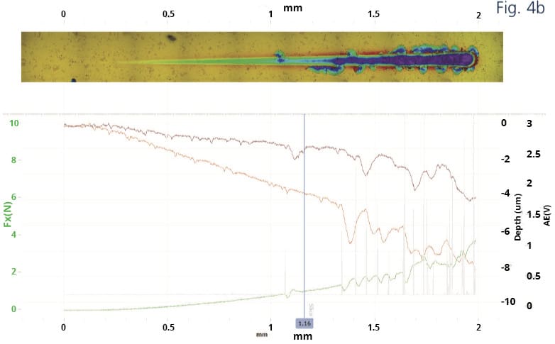
Figure 4a b: Plots of Penetration depth, Scratch load, coefficient of friction, Acoustic emission along with Critical loads (vertical lines)
for DLC 2 (4a) and TIN (4b) samples
for DLC 2 (4a) and TIN (4b) samples
In This Case Three Types of Failures Are Recorded:
Lc1: First cracks in the coating

Figure 5: First failure in DLC 2 coating (Lc1)
Lc2: First chipping of the coating

Figure 6a: First chipping of DLC coating (Lc2; adhesive)

Figure 6b: First chipping of TiN coating (Lc2, cohesive)

Figure 7: Complete removal of DLC coating (Lc3)
Lc3: Full removal of the coating

Scratch Evaluation Test Summary and Conclusion

Figure 8: Penetration and residual depths for DLC 1 and TiN samples illustrate the recovery of the samples
For the DLC sample, the change in coefficient of friction and acoustic emission are great indicators for the first failure (Lc1), while confocal image provides better details for Lc2 and Lc3. On the TiN sample, acoustic emission provides a good signal to detect the first 2 failures (Lc1 and Lc2) while optical observation in bright field provides necessary detection for Lc3. The comparison of the scratch penetration depth (under load) and the residual depth of the groove left in the sample provides valuable information on the recovery of the sample after the scratch deformation.
This plot can be used to characterize the elastic recovery of the coating / substrate system. A summary of the critical loads provides a good comparison of the samples as shown in Figure 9.

While Lc1 do not present significant difference between the samples, Lc2 and Lc3 show the superiority of TiN sample above the DLC samples. The adhesion of DLC 1 (Lc2) is the worst between all three samples.
Conclusions
The scratch testing technique is a valuable tool to differentiate coating behaviors. The stresses generated during the scratch test provide information on the strength of the coating first, but also on the adhesion between coating and substrate as demonstrated above. The careful analysis of all signals recorded during a scratch test in addition to the robust imaging provided by confocal and bright field imaging allows for the most advanced understanding of coating / substrate systems behaviors. The 3D scratch tester, through Scratch testing of hard coatings, determined the scratch adhesion and cohesion of hard coatings.
International standards
ASTM C 1624-05
“Standard test method for adhesion strength and mechanical failure modes of ceramic coatings by quantitative single point scratch testing.”
“Standard test method for adhesion strength and mechanical failure modes of ceramic coatings by quantitative single point scratch testing.”

The Scratch and Indentation Tester Has More To Offer
Learn more about our Indentation and Scratch Tester, the SMT-5000.
Need Versatile Scratch and Indentation Testing?
Take a look at the Multi Function Tribometer, the MFT-5000.
Möchten Sie mehr erfahren?
Kontaktieren Sie uns und fordern Sie eine Demonstration an.
Leading innovation in surface and materials testing instrumentation.
recommended
Information
© Copyright 2021 Rtec-Instruments - All Rights Reserved