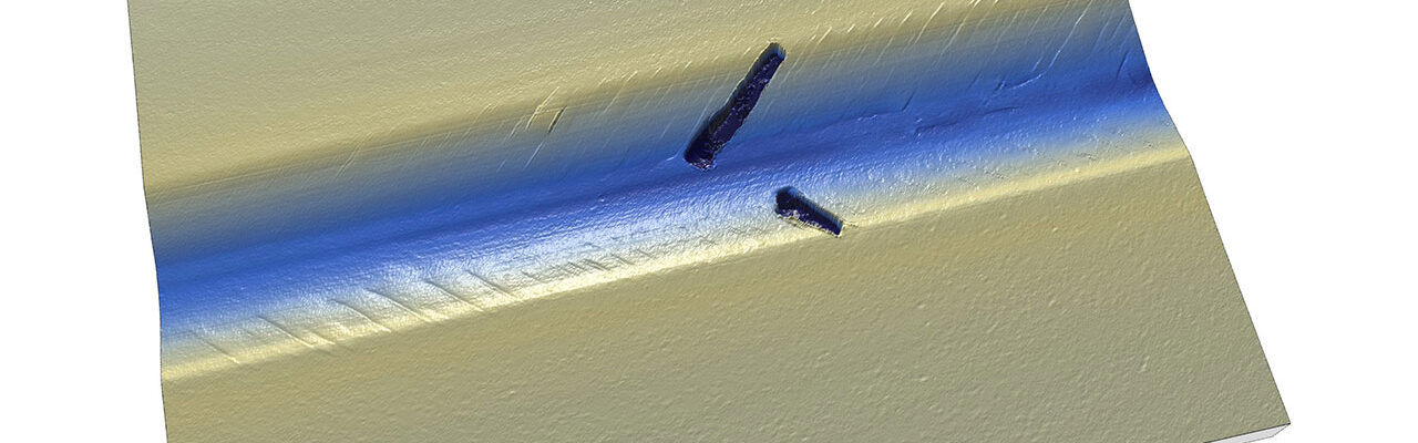
Introduction
Ceramic coatings deposited by PVD (Physical Vapor Deposition) or CVD (Chemical Vapor Deposition) techniques — referred to here as “hard coatings” — are widely used for their wear and corrosion resistance and low friction properties. Furthermore, different parameters influence their wear, friction, and chemical resistance. These include composition, microstructure, thickness, internal stresses, adhesion strength, hardness, ductility, toughness, and thermal stability.
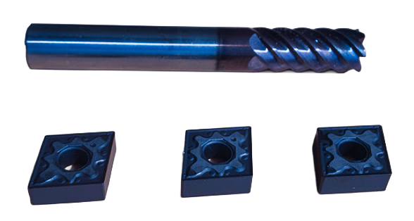
Typical applications of PVD coatings: inserts and cutting tools
Different methods exist for characterizing the mechanical properties of hard coatings. Tribological measurements furthermore provide useful information on coefficient of friction and wear — essential properties for real applications. Instrumented indentation testing additionally provides information on hardness and elastic modulus. However, none of these methods give meaningful information on deposition process quality control.
Scratch testing measures coating adhesion and scratch resistance, consequently providing unmatched information on the mechanical integrity of the coating-substrate system. Different aspects of the scratch test method for quality control are therefore detailed in this Application Note.
Principles of Testing
For manufacturing parts, ensuring identical parts are produced each time is of the highest importance. Scratch testing furthermore allows precise quantification of hard coating performance — including adhesion, consistency of internal stresses, and deposition process quality (substrate cleaning, surface quality, deposition equipment condition).
For quality control of hard coatings, the primary reference is ISO 20502 (and ASTM C1624-05). This norm consequently defines the scratch test as follows:
“The scratch test is designed for the assessment of the mechanical integrity of coated surfaces. The test method consists of generating scratches with a stylus of defined shape — usually a Rockwell C diamond — by drawing it across the coating-substrate surface under constant or progressive normal force. Failure events are furthermore detected by direct microscopic observation, and additionally by acoustic emission and/or friction force measurement.”
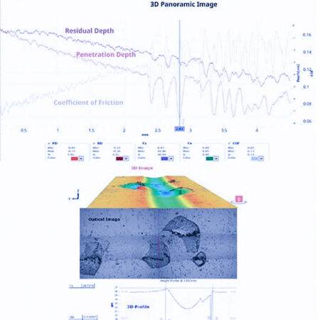
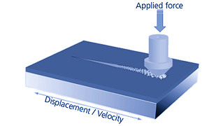
A test with constant or increasing forces can be considered. The interest of the increasing force is to determine in a single test the critical loads, and therefore the critical stresses, at which the cohesive and/or adhesive failures are observed. By a relatively quick test, the critical load for which the coating adhesion is failing can be measured, as shown on Fig. 3.
Characterization Method
“The force is applied to the stylus so as to promote adhesive and/or cohesive failure of the coating substrate system.“
Differences between failure modes are interesting to observe: adhesive failure (delamination at the interface coating-substrate, typically observed on DLC coatings) or cohesive failure (spallation inside the coating, typically observed on TiN coatings) provide an interesting view on the mechanical strength of the sample (see Fig. 4).
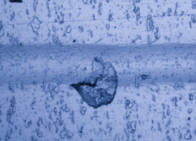
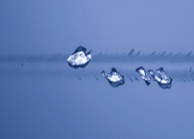
“The driving forces for the failure of the coating substrate system in the scratch test are a combination of elastic-plastic indentation stresses, frictional stresses and the residual internal stress present in the coating. The normal force at which failure occurs is called the critical normal force Lc.”
The critical normal force, Lc, is linked therefore to the mechanical integrity of a coating-substrate system (or multilayer coating-substrate). The mechanical stresses in the system can be schematically represented as on Fig. 5.
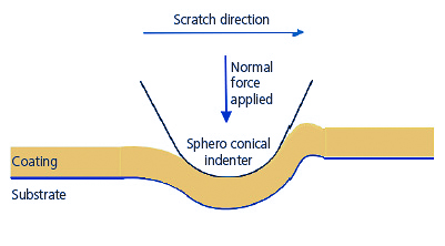
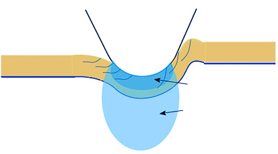
“It is quite common to characterize the onset of cracking by the critical normal force Lc1, while the onset of coating detachment defines the critical normal force Lc2. In general, a series of failure modes are observed and used to study the mechanical behavior of the coated surface, where the onset of the nth failure mode defines the critical normal force, Lcn.”
The Lc1 is generally considered as the appearance of the first cracks, the Lc2 as the first delamination or spallation, and the Lc3 as the full delamination. Examples of Lc1, Lc2 and Lc3 are illustrated on Figure 6a-c.
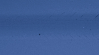
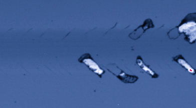
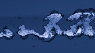
It is possible that one of the 3 main critical normal forces, Lc(n), may not be clearly visible by optical observation or detected easily by one of the optional sensors (AE or friction force). A short study would allow to evaluate quickly the most adapted parameters for an easy detection in Quality Control (visual, AE, friction and/or depth).
The determination of the critical normal force, Lc(n), also commonly accepted name of critical loads, Lc(n), could represent the aspect of testing which is the most subject to interpretation. The challenge may lie on two aspects:
- Difficulty of detection: typical cracks in hard coatings can be detected with the Acoustic Emission (AE) sensor but can be difficult to observe optically. It is therefore worthwhile to investigate which detection method (microscopy,
penetration depth, AE or friction) is the more valuable for this detection; - Misinterpretation: some failure modes can be interpreted differently by various users.
But in Quality Control, these errors can be easily eliminated from the beginning on the first study. The modes of failures on a specified coating-substrate system are highly reproducible (i.e TiN coatings show typical cohesive failures while DLC coatings tend to display adhesive failures). It is also easier to decide which Lc(n) are the most meaningful without possible misinterpretation.
Indenter Tip Characterization
One of the essential experimental parameter of influence of the scratch testing method, which can be overlooked, is the exact geometry of the spherical indenter tip and its regular control.
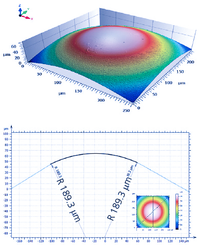
The test by itself corresponds to a strong mechanical interaction between a sphero-conical indenter and a coating surface, for which the results is highly dependent on small variations of the local contact area. Therefore, it is extremely important to regularly check the quality of the tip.
Rtec-Instruments is proposing an integrated confocal microscope to the scratch tester, which allows a fast indenter tip control with a high resolution 3D image. Tip damages or contaminations can be observed easily. A regular cleaning of the tip by ultrasonic bath and/or mechanical polishing is helping to ensure an effective consistent contact area for scratch tests. This process
can be implemented in the control procedure of the scratch testing method.
Multi-Pass Scratch Test or Tribological Test
The specimen is subjected to repeated scratching, within the same scratch track, under a constant subcritical normal force. Using a normal force of 50 % of that determined under the progressive-force scratch mode, an indenter traverse speed of 10 mm/min and a scratch length of at least 3 mm, the sample is tested until failure occurs. This mode represents a low-cycle fatigue-type contact, which is closer to the real working conditions, but also more equivalent to a tribological test. The scratch tester can then be used like a tribometer in a linear reciprocating oscillating mode.
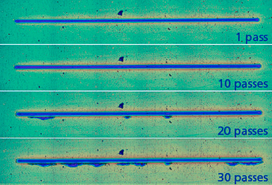
Figure 11a. Evolution of a mutlipass constant scratch at 15 N on TiN

Figure 11b. Superposition of the profile during multipass constant scratch test at 15 N on TiN coating
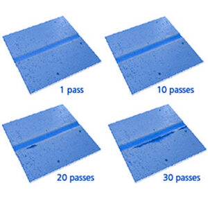
Figure 11c. 3D image of the multiscan at 15 N
Interest of Quality Control with the Scratch Test Method and Conclusions
Coating-substrate parameters relevant to the scratch test include the mechanical properties of substrate and coating, coating thickness, internal stresses, and friction coefficient between coating and indenter tip. For quality control of hard coatings, any modification of the deposition process can furthermore be detected precisely with scratch testing.
It is important to note that the sample corresponds to the combination of coating and substrate. Results are therefore highly dependent on their combined properties. For example, coating thickness influences residual stresses, which consequently modify the critical loads measured during scratch testing. The hardness and elastic modulus of the substrate additionally influence elastic deformations created in the coating.
As a result, critical load values shift to higher values when substrate hardness increases. Coating thickness also has an influence, but on a more logarithmic scale. Samples must therefore be considered as a mutual combination of coating and substrate.
Tribometers and indentation testers provide information on PVD or CVD coating mechanical properties. However, none of these methods give meaningful information on deposition process quality control. Scratch testing consequently measures not only coating adhesion but also the mechanical strength of the coating-substrate system. It therefore represents the most valuable QC tool for ensuring reproducibility of the deposition process.